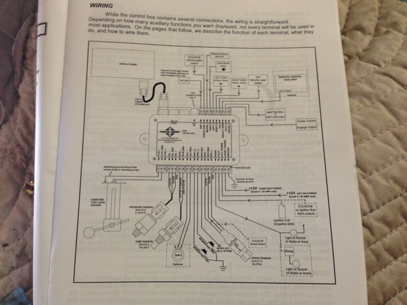
Dakota Digital Vhx Wiring Diagram
1996 Ezgo Txt 36 Volt Wiring Diagram, 1996 EZGO TXT DCS wiring problem, 9.48 MB, 06:54, 7,299, Tony Conway, 2020-04-24T01:31:46.000000Z, 19, 1996 Ez Go Wiring Diagram Sample, wholefoodsonabudget.com, 1920 x 1515, jpeg, wiring diagram ez 1996 ezgo gas txt 36v wire sample, 20, 1996-ezgo-txt-36-volt-wiring-diagram, Anime Arts
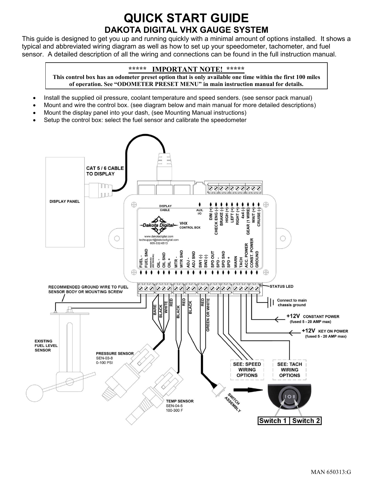
Quick start wiring diagram this drawing is a quick overview of the basic wiring for your new dakota digital vhx system. Once completed all the basic functions should operate; Speed, tachometer, fuel level, voltmeter, water temp, and oil pressure. For further wiring assistance please read the remainder of the manual.
Once completed all the basic functions should operate; Speed, tachometer, fuel level, voltmeter, water temp, and oil pressure. For further wiring assistance please read the remainder of the manual. Bim time channel, use the following steps (see vhx operations manual or the bim expansion module manual for more details on setting bim channel time): While holding vhx switch 1, turn the key on to turn on vhx system and enter setup. Press and release switch 1 until the setup bim option and press and hold switch to select it. Dakota digital speedometer wiring diagram from www. thehulltruth. com effectively read a electrical wiring diagram, one provides to find out how the particular components in the system operate. For example , when a module is powered up and it sends out a new signal of fifty percent the voltage and the technician does not know this, he would think he has a problem, as this. If you are using this sensor, the white wire is the speed signal;
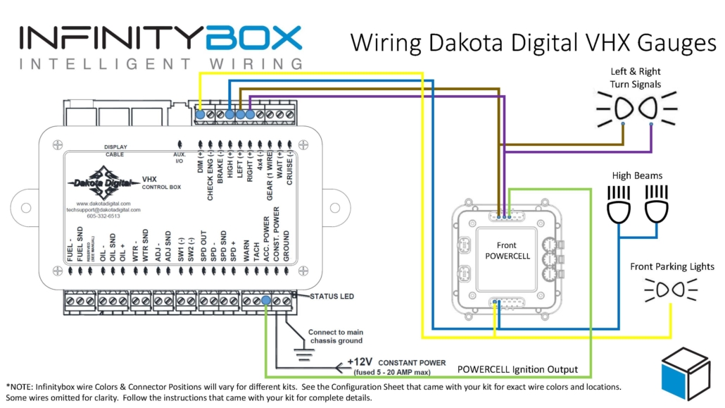
Wiring Dakota Digital VHX Gauges - Infinitybox

We Install a Dakota Digital VHX System Into a 1986 Camaro - Hot Rod Network

Dakota Digital VHX User manual | Manualzz
Dakota Digital VHX Installation And Operation Manual Download - Page 5

Bullnose Enthusiasts Forum - Dakota Digital Gauges for 1980-1986 F-Series
Dakota Digital Wiring Diagram - 3
Dakota Digital VHX Installation And Operation Manual Download - Page 8

Diagram for harness+dakota digital+vintage air+painless? - Lateral-g Forums
Dakota Digital Wiring Diagram - VIMAXBEST
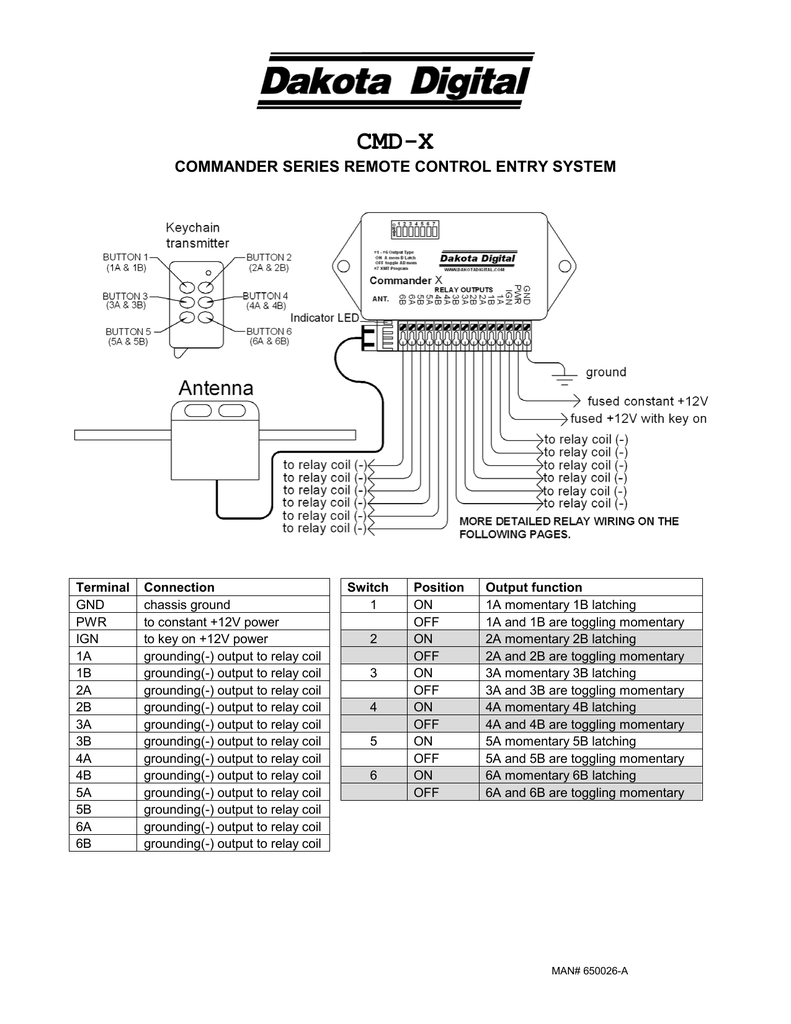
Dakota Digital button wiring: sw1 sw2 - LS1TECH - Camaro and Firebird Forum Discussion
